I/O Management
v I/O Hardware:
- I/O devices can be roughly
categorized as storage, communications, user-interface, and other.
- Devices communicate with the
computer via signals sent over wires or through the air.
- Devices connect with the computer
via ports,
e.g. a serial or parallel port.
- A common set of wires connecting
multiple devices is termed a bus.
- Buses include rigid protocols for
the types of messages that can be sent across the bus and the procedures
for resolving contention issues.
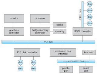
- Figure below illustrates three of the four bus
types commonly found in a modern PC:
- The PCI bus connects
high-speed high-bandwidth devices to the memory subsystem (and the CPU.)
- The expansion bus connects
slower low-bandwidth devices, which typically deliver data one character
at a time (with buffering.)
- The SCSI bus connects
a number of SCSI devices to a common SCSI controller.
- A daisy-chain bus, (not
shown) is when a string of devices is connected to each other like beads
on a chain, and only one of the devices is directly connected to the host.
·
One way of communicating with
devices is through registers associated
with each port.
·
Registers may be one to four
bytes in size, and may typically include ( a subset of ) the
following four:
1. The data-in
register is read by the host to get input from the
device.
2.
The data-out register is
written by the host to send output.
3.
The status register has
bits read by the host to ascertain the status of the device, such as idle,
ready for input, busy, error, transaction complete, etc.
4.
The control register has
bits written by the host to issue commands or to change settings of the device
such as parity checking, word length, or full- versus half-duplex operation.
·
Another technique for
communicating with devices is memory-mapped
I/O.
·
In this case a certain
portion of the processor's address space is mapped to the device, and
communications occur by reading and writing directly to/from those memory
areas.
·
Memory-mapped I/O is
suitable for devices which must move large quantities of data quickly, such as
graphics cards.
·
Memory-mapped I/O can be
used either instead of or more often in combination with traditional registers.
For example, graphics cards still use registers for control information such as
setting the video mode.
·
A potential problem exists
with memory-mapped I/O, if a process is allowed to write directly to the
address space used by a memory-mapped I/O device.
·
(Note: Memory-mapped I/O
is not the same thing as direct memory access, DMA.)
v Polling:
·
One simple means of
device handshaking involves
polling:
- The host repeatedly checks the busy bit on
the device until it becomes clear.
- The host writes a byte of data into the
data-out register, and sets the write bit in the command
register (in either order. )
- The host sets the command ready bit in
the command register to notify the device of the pending command.
- When the device controller sees
the command-ready bit set, it first sets the busy bit.
- Then the device controller reads
the command register, sees the write bit set, reads the byte of data from
the data-out register, and outputs the byte of data.
- The device controller then
clears the error
bit in the status register, the command-ready
bit, and finally clears the busy bit, signaling the completion of the
operation.
- Polling can be very fast and
efficient, if both the device and the controller are fast and if there is
significant data to transfer.
- It becomes inefficient, however, if the
host must wait a long time in the busy loop waiting for the device, or if
frequent checks need to be made for data that is infrequently there.
v Interrupts:
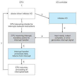
- Interrupts
allow devices to notify the CPU when they have data to transfer or when an
operation is complete, allowing the CPU to perform other duties when no
I/O transfers need its immediate attention.
- The
CPU has an interrupt-request
line that is sensed after every instruction.
- A device's controller raises an
interrupt by asserting a signal on the interrupt request line.
- The CPU then performs a state
save, and transfers control to the interrupt handler routine
at a fixed address in memory. (The CPU catches the
interrupt and dispatches the
interrupt handler.)
- The interrupt handler determines
the cause of the interrupt, performs the necessary processing, performs a
state restore, and executes a return from interrupt instruction
to return control to the CPU.(The interrupt handler clears the
interrupt by servicing the device.)
Fig: Interrupt-driven I/O cycle.
o Most CPUs now have two interrupt-request lines: One that is non-maskable for
critical error conditions and one that is maskable, that
the CPU can temporarily ignore during critical processing.
o The interrupt mechanism accepts an address, which is usually one of a small set of numbers for an offset into a table called the interrupt vector. This table (usually located at physical address zero?) holds the addresses of routines prepared to process specific interrupts.The number of possible interrupt handlers still exceeds the range of defined interrupt numbers, so multiple handlers can be interrupt chained.
o Modern interrupt hardware also supports interrupt priority levels,
allowing systems to mask off only lower-priority interrupts while servicing a
high-priority interrupt, or conversely to allow a high-priority signal to
interrupt the processing of a low-priority one.
o System calls are
implemented via software interrupts, also
known as traps.
v Direct
Memory Access (DMA):
- For
devices that transfer large quantities of data ( such as disk controllers
), it is wasteful to tie up the CPU transferring data in and out of
registers one byte at a time.
- Instead this work can be
off-loaded to a special processor, known as the Direct Memory Access, DMA,
Controller.
- The host issues a command to the
DMA controller, indicating the location where the data is located, the
location where the data is to be transferred to, and the number of bytes
of data to transfer. The DMA controller handles the data transfer, and
then interrupts the CPU when the transfer is complete.
- A simple DMA controller is a
standard component in modern PCs, and many bus-mastering I/O
cards contain their own DMA hardware.
- Handshaking between DMA
controllers and their devices is accomplished through two wires called the
DMA-request and DMA-acknowledge wires.
- While the DMA transfer is going
on the CPU does not have access to the PCI bus (including main memory),
but it does have access to its internal registers and primary and secondary
caches.
- DMA can be done in terms of
either physical addresses or virtual addresses that are mapped to physical
addresses. The latter approach is known as Direct Virtual Memory Access,
DVMA, and allows direct data transfer from one
memory-mapped device to another without using the main memory chips.
- Direct DMA access by user processes can speed up operations, but is generally forbidden by modern systems for security and protection reasons (i.e. DMA is a kernel-mode operation).
v Block and Character Devices:
- Block devices:
- Are accessed a block at a time,
and are indicated by a "b" as the first character in a long
listing on UNIX systems.
- Operations supported include read
( ), write ( ), and seek ( ).
- Accessing blocks on a hard drive
directly (without going through the file system structure) is
called raw
I/O, and can speed up certain operations by bypassing
the buffering and locking normally conducted by the OS.
- A new alternative is direct I/O, which
uses the normal file system access, but which disables buffering and
locking operations.
- Memory-mapped file I/O can be
layered on top of block-device drivers.
- Character devices:
- Are accessed one byte at a time,
and are indicated by a "c" in UNIX long listings.
- Supported operations include get()
and put(), with more advanced functionality such as reading an entire
line supported by higher-level library routines.
v Blocking
and Non-blocking I/O:
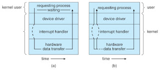
- With blocking I/O a
process is moved to the wait queue when an I/O request is made, and moved
back to the ready queue when the request completes, allowing other
processes to run in the meantime.
- With non-blocking I/O the
I/O request returns immediately, whether the requested I/O operation has (completely)
occurred or not. This allows the process to check for available data
without getting hung completely if it is not there.
- One
approach for programmers to implement non-blocking I/O is to have a
multi-threaded application, in which one thread makes blocking I/O calls (
say to read a keyboard or mouse ), while other threads continue to update
the screen or perform other tasks.
- A
subtle variation of the non-blocking I/O is the asynchronous I/O, in
which the I/O request returns immediately allowing the process to continue
on with other tasks, and then the process is notified when the I/O
operation has completed and the data is available for use.
- The regular non-blocking I/O returns immediately with whatever results are available, but does not complete the operation and notify the process later.
Fig: Two I/O methods: (a) synchronous and (b) asynchronous.
v Buffering:
- Buffering
of I/O is performed for ( at least ) 3 major reasons:
- Speed differences between two devices. A
slow device may write data into a buffer, and when the buffer is full, the
entire buffer is sent to the fast device all at once. So that the slow
device still has somewhere to write while this is going on, a second
buffer is used, and the two buffers alternate as each becomes full. This
is known as double
buffering. (Double buffering is often used in (animated)
graphics, so that one screen image can be generated in a buffer while the
other (completed) buffer is displayed on the screen. This prevents the
user from ever seeing any half-finished screen images. )
- Data transfer size differences.
Buffers are used in particular in networking systems to break messages up
into smaller packets for transfer, and then for re-assembly at the
receiving side.
- To support copy semantics. For example, when an application makes a request for a disk write, the data is copied from the user's memory area into a kernel buffer. Now the application can change their copy of the data, but the data which eventually gets written out to disk is the version of the data at the time the write request was made.
v Caching:
- Caching involves keeping a copy of
data in a faster-access location than where the data is normally stored.
- Buffering and caching are very
similar, except that a buffer may hold the only copy of a given data item,
whereas a cache is just a duplicate copy of some other data stored
elsewhere.
- Buffering and caching go
hand-in-hand, and often the same storage space may be used for both
purposes. For example, after a buffer is written to disk, then the copy in
memory can be used as a cached copy, (until that buffer is needed for
other purposes.)


No comments:
Post a Comment