Monday, 9 November 2020

What are the differences between Paging and Segmentation in OS?


Differences between Paging and Segmentation:

Paging

Segmentation

The main memory is partitioned into frames or blocks.

The main memory is partitioned into segments.

The logical address space is divided into pages by compiler or a memory management unit.

The logical address space is divided into segments, specified by the programmer.

This scheme suffers from internal fragmentation for page breaks.

This scheme suffers from external fragmentation.

The operating system maintains a free frames list. So, it need not search for free frames.

The operating system maintains the particulars of available memory.

The operating system maintains a page map table for a mapping between frames and pages.

Operating system maintains a segment map table for mapping purposes.

This scheme does not support the user’s view of memory.

It supports user’s view of memory.

Processor uses the page number and displacement to calculate absolute address (P, D).

Processor uses the segment number and displacement to calculate the absolute address(S, D).

 Multi-level paging is possible.

Multi-level segmentation is also possible but no use.

What is Protection in Paging


Protection:


The word protection means security from unauthorized references from main memory. To provide protection, the OS follows different types of mechanisms. In paging memory management scheme, the operating system provides protection bits that are associated with each frame. Generally, these bits are kept in a page table. Sometimes, these bits are said to be valid / not valid bit. Consider the following fig:

Protection in paging

Fig: Protection in paging

The page map table consists of a specified field that is valid/ invalid bit. If the bit shows valid, it means the particular page is loaded in main memory. If it shows invalid, it means the page is not in the process’s logical address space. Illegal addresses are trapped by using the valid / invalid bit. The operating system sets this bit for each page to allow or disallow access to that page.


OS Segmentation with Paging


Segmentation with Paging:


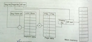
Both paging and segmentation have their advantages and disadvantages. It is better possible to combine these two schemes to improve on each. The combined scheme was ‘Page the segments’. Each segment in this scheme is divided into pages and each segment maintains a page table. So, the logical address is divided into 3 parts <S, P, D>.One is the segment number (S), second is the page number (P) and another is a displacement or offset (D). Consider the following fig:

Paged Segmentation

Fig: Paged Segmentation


The logical address space is divided into three segments number from 0 to 2. Each segment maintains a page table. The mapping between page and frame is done by page table. For ex: the frame number 8 shows the address (1, 3); where 1 stands for segment and 3 stands for page number. The main advantage of this scheme is to avoid fragmentation. It supports user view of memory. The hardware support of this combined scheme is shown in the following figure.


Paged segmentation memory management scheme

Fig: Paged segmentation memory management scheme


What is Segmentation in OS?


Segmentation:


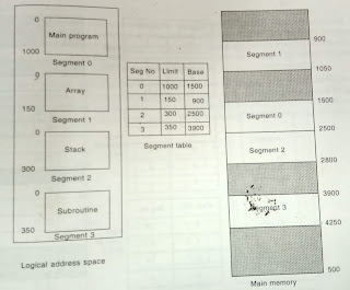
A segment can be defined as a logical grouping of instructions, such as subroutine, array, or data area.  Every program (job) is a collection of these segments. Segmentation is the technique for managing these segments. For ex: consider the following fig:

Segmented address space

Fig: Segmented address space


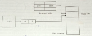
Each segment has a name and a length. The address of the segment specifies both segment name and the offset within the segment. For ex: the length of the segment ‘Main’ is 100 KB, ‘Main’ is the name of the segment. The operating system searches the entire main memory for a free space to load a segment. This mapping is done by a segment table. The segment table is a table where each entry of the segment table has a segment ‘Base’ and a segment ‘Limit’.


The segment ‘Base’ contains the starting physical address where the segment resides in memory. The segment ‘Limit’ specifies the length of the segment.


Segment table

Fig: Segment table


The logical address consists of two parts: segment number(S), and an offset into that segment (D). The segment number(S) is used as an index into the segment table. For ex: consider the fig.


Segmentation example

Fig: Segmentation example


The logical address space (a job) is divided into 4 segments, numbered from 0 to 3. Each segment has an entry in the segment table. The ‘Limit’ specifies the size of the segment and the ‘Base’ specifies the starting address of the segment. For ex: segment ‘0’ is loaded in the main memory from 1500 KB to 2500 KB. So, 1500 KB is the base and 2500 - 1500= 1000 KB is the limit.


Advantages of Segmentation:

  1. Eliminate fragmentation:  by moving segments around, fragmented memory space can be combined into a single free area.
  2. Segmentation supports virtual memory.
  3. It allows dynamically growing segments.
  4. It facilitates shared segments.
  5. Dynamic linking and loading of the segments is possible.

What is a Paging technique in OS?


Paging:


Paging is an efficient memory management scheme because it is a non-contiguous memory allocation method. The previous (single partition, multiple partition) methods support the contiguous memory allocation. The entire process is loaded in a partition. But in the paging, the process is divided into smaller parts and these are loaded into elsewhere in the main memory.


The basic idea of paging is the physical memory (main memory) is divided into fixed size blocks called frames, the logical address space (user job) is divided into fixed size blocks called pages; but page size and frame size should be equal. The size of the frame or a page is dependent on operating system. Generally, the page size is 4 KB.


In this scheme, OS maintains a data structure i.e. a page table. It is used for the mapping purpose. The page table specifies some useful information. It tells us which frames are allocated, which frames are available, and how many total frames are there, etc. The general page table consists of two fields, one is page number and other is frame number. Each operating system has its own methods for storing page tables. Most of them allocate a page table for each process.


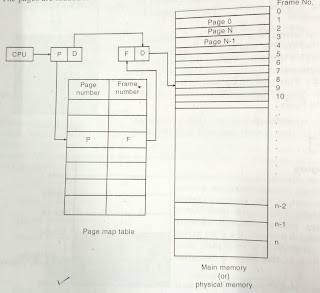
Every address generated by the CPU is divided into two parts. One is page number (P) and second is page offset or displacement (D). The page number is used as an index in a page table. Consider the following fig:

Paging structure

Fig: Structure of paging scheme


The mapping between page number and frame number is done by page map table. The page map table specifies which page is loaded in which frame, but displacement is common. Consider the below example:


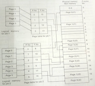
There are two jobs in the ready queue. The job sizes are 16 KB and 24 KB respectively. The page size is 4 KB and available memory is 72 KB (18 frames). So, job1 is a divided into 4 pages and job2 is divided into 6 pages. Each process maintains a program table. Consider the below figure for better understanding:


Paging example

Fig: An example of paging


4 pages of job1 are loaded in different locations in main memory. The OS provides a page table for each process. The page table specifies the location in main memory. The capacities of main memory in our example are 18 frames. But, the available jobs are two (10 pages). So, the remaining 8 frames are free. The scheduler can use these free frames to some other jobs.


 Advantages:

  1. It supports the time sharing system.
  2. It does not affect from fragmentation.
  3. It supports virtual memory.
  4. Sharing of common code is possible.


 Disadvantages:

  1. This scheme may suffer from page breaks. For ex: the logical address space is 17 KB, the page size is 4 KB. So, this job requires 5 frames. But, the 5th frame consists of only 1KB. So, the remaining 3 KB is wasted. This is called as a page break.
  2. If the numbers of pages are high, it is difficult to maintain page tables.


 Shared Pages:


In multiprogramming environment, it is possible to share the common code by number of processes at a time, instead of maintaining the number of copies of same code. The logical address space is divided into pages.  These pages can be shared by number of processes at a time. The pages which are shared by the number of processes is said to be shared pages.


For ex: consider a multiprogramming environment. It consists of a 10 users. Out of 10 users, 3 users wish to execute a text editor. They want to make their bio data in text editor. Assume that a text editor requires 150 KB and the user bio-data occupies 50 KB of data space. So, they would require 3x (150 + 50) = 600 KB. But, in shared paging, the text editor is shared to all jobs so it requires 150 KB, and the user files require 150 KB (50x3=150 KB).


Therefore, (150 + 150) = 300 KB is enough to manage these three jobs instead of 600 KB. So, this shared pages mechanism saves 300 KB of space. Consider the below figure for a better understanding:


Sharing a code in paging environment

Fig: Sharing a code in paging environment


The page size and the frame size is 50 KB. So, 3 frames are required for text editor and 3 frames are required for user files. Each process (P1, P2, and P3) has a page table. The page table shows the frame numbers. The first 3 frame numbers in each page table i.e. 3, 8, 0 are common. It means the three processes share the three pages. Main advantage of shared pages is efficient memory utilization is possible using this technique.


What is Compaction in OS?


Compaction:


Compaction is a technique of collecting all the free space together in one block. This block or partition can be allotted to some other jobs. For ex: consider the following fig.


Memory representation(a)

Fig (a): Memory representation


The total internal fragmentation in this scheme is (100 + 75 + 75 = 250). The total external fragmentation is 400 + 350 + 625 = 1375 KB. Collect the internal and external fragmentation together in one block (250 + 1375 = 1625 KB). This type of mechanism is said to be compaction. Now the compacted memory is 1625 KB.


Consider the below fig. Now, the scheduler can load job J3 (1200 KB) in compacted memory. So, efficient memory utilization is possible using compaction.

Compacted memory

Fig (b): Compacted memory


Multiple Partitions Memory Management: Fixed Equal, Fixed Variable and Dynamic Partition Schemes


Multiple Partitions Memory Management:


This method can be implemented in three ways. These are:


  1. Fixed equal multiple partitions memory management
  2. Fixed variable multiple partitions memory management
  3. Dynamic multiple partitions memory management


A.   Fixed Equal Multiple Partitions Memory Management Scheme:


In this memory management scheme, the OS occupies lower memory, and the rest of main memory is available for user space. The user space is divided into fixed partition. The partition sizes are depended on operating system. For ex: if the total main memory size is 6 MB, 1MB occupied by the operating system. The remaining 5 MB is partitioned into 5 equal partitions (5x1 MB). J1, J2, J3, J4, J5 are the five jobs to be loaded into main memory. Their sizes are:

Job

Size

J1

450 KB

J2

1000 KB

J3

1024 KB

J4

1500 KB

J5

500 KB


Consider the following fig. for better understanding.


Main memory allocation

Fig: Main memory allocation


Internal and External fragmentation:


Job J1 is loaded into partition 1. The maximum size of the partition 1 is 1024 KB; the size of J1 is 450 KB. So, 1024 - 453=574 KB space is wasted.  This wasted memory is said to be ‘internal fragmentation’.


But, there is no enough memory to load job J4 because; the size of job J4 is greater than all the partitions. So, the entire partition i.e. partition 5 is wasted. This wasted memory is said to be ‘external fragmentation’.


Therefore, total internal fragmentation = (1024 - 450) + (1024 - 1000) + (1024 - 500)

        = 574 + 24 + 524

        = 1122 KB


Therefore, the external fragmentation for this scheme is = 1024 KB


A partition of main memory is wasted within a partition is said to be ‘internal fragmentation’ and the wastage of an entire partition is said to be ‘external fragmentation’.


Advantages:

  1. This scheme supports multiprogramming.
  2. Efficient utilization of the processor and IO devices.
  3. It requires no special costly hardware.
  4. Simple and easy to implement.


 Disadvantages:

  1. This scheme suffers from internal as well as external fragmentation.
  2. The single free area may not be large enough for a partition.
  3. It does require more memory than a single partition method.
  4. A job partition size is limited to the size of physical memory.


B.  Fixed Variable Partition Memory Management Scheme:


In this scheme, the user space of main memory is divided into number of partitions, but the partition sizes are of different lengths. Operating system keeps a table indicating which partition of memory are available and which are occupied. When a process arrives and needs a memory, we search for a partition large enough for this process. If we find one, allocate the partition to that process. For ex: assume that we have 4000 KB of main memory available and operating system occupies 500 KB. The remaining 3500 KB leaves for a user processes as shown in the following fig:


Scheduling example

Fig: Scheduling example


  1. Out of 5 jobs J2 arrives first (5ms), the size of J2 is 600 KB. So, search all the partitions from lower memory to higher memory for a large enough partition.  P1 is greater than J2, so load J2 in P1.
  2. In rest of jobs, J1 is arriving next (10ms). The size is 825 KB. So, search the enough partition. P4 is large partition, so load J1 into P4.
  3. J5 arrives next, the size is 650 KB. There are no large enough partitions to load that job. So, J5 has to wait until enough partition is available.
  4. J3 arrives next, the size is 1200 KB. There are no large enough partitions to load it.
  5. J4 arrives last, the size is 450 KB. Partition P3 is large enough to load it. So, load J4 into P3.


Consider the following fig. for better understanding.


Memory allocation

Fig: Memory allocation


Partitions P1, P2, P5, and P6 are totally free. There are no processes in these partitions. This wasted memory is said to be external fragmentation. The total external fragmentation is 1375(400 + 350 + 625).


The total internal fragmentation is: (700 - 600) + (525 - 450) + (900 - 825) = 250


Now you may have a doubt that the size of J2 is 600 KB and it is loaded in partition P1 as shown in the above figure. In this case, the internal fragmentation is 100 KB. But if it is loaded in P6, then the internal fragmentation is only 25 KB. Why it is loaded in P1? Three algorithms are available to answer this question. These are first fit; best fit and worst fit algorithms.

First fit:

·         Allocate the partition that is big enough.

·         Searching can start either from lower memory or higher memory.

·         We can stop searching as soon as we find a free partition that is large enough.


Best fit:

·         Allocate the smallest partition that is big enough or select a partition which is having the least internal fragmentation.


 Worst fit:

·         Search the entire partitions and select a partition which is the largest of all or select a partition which is having the maximum internal fragmentation.


Advantages:

  1. This scheme supports multi programming.
  2. Efficient processor utilization and memory utilization is possible.
  3. Simple and easy to implement.


Disadvantages:

  1. This scheme is suffers from internal and external fragmentation.
  2. There is a possibility for large external fragmentation.


C.  Dynamic Partition Memory Management Scheme:


To eliminate some of the problems with fixed partitions, an approach known as dynamic partitioning was developed. In this method, partitions are created dynamically, so that each process is loaded into a partition of exactly the same size of that process. In this scheme, the entire user space is treated as a “big hole”. The boundaries of partitions are dynamically changed, and the boundaries are dependent on the size of the processes. Consider the following example:


Memory allocation

Fig: Memory allocation


Job J2 arrives first, so load the J2 into memory. Next J1 arrives and it is loaded into memory. Similarly, J5, J3, and J4 arrive respectively. Consider the following fig:


Memory representation

Fig: Memory representation


In above fig: (a), (b), (c), (d) jobs J2, J1, J5, and J3 are loaded. The last job is J4 and its size is 450 KB. But, the available memory is 225 KB. It is not enough to load J4, so the job J4 has to wait until the memory becomes available. Assume that after some time J5 has finished and it has released its memory. So the available memory now becomes 225 + 650 = 875 KB. It is enough to load job J4. Consider the following fig:

Memory representation - 2

Fig: (e) and (f)


 Advantages:

  1. In this scheme partitions are changed dynamically so that this scheme doesn't suffer from internal fragmentation.
  2. Efficient memory and processor utilization is possible in this scheme.


 Disadvantages:

  1.  This scheme suffers from the problem of external fragmentation.


Single Partition Memory Allocation Method in OS


Memory Allocation Methods in OS:


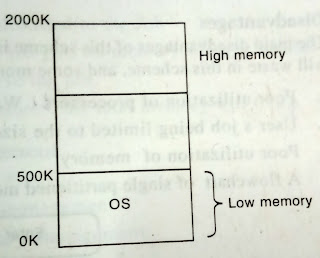
The main memory must accommodate both operating system and various user processes. The operating system may be placed in either lower memory or higher memory. It is common to place the operating system in lower memory. Consider the following fig:

OS in lower memory

Fig: OS in lower memory


 There are many methods available for memory allocation. These are as follows:


1.   Single Partition Allocation:


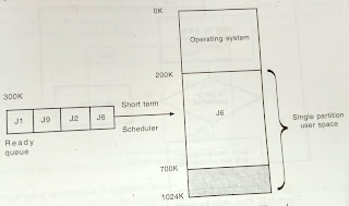
In this memory allocation method, the operating system resides in the lower memory and the remaining memory is treated as a single partition. This single partition is available for user space. Only one job can be loaded in this user space. Consider the following fig. that depicts single partition allocation.


Single partition memory allocation

Fig: Single partition memory allocation


The short term scheduler or CPU scheduler selects a job from the ready queue for execution. The dispatcher loads that job into main memory and connects the CPU to that job. The main memory consists of only one process at a time because; the user space is treated as a single partition.


 Advantages:


·         The main advantage of this scheme is its simplicity.

·         It does not require a great expertise to understand or use such a system.


 Disadvantages:


  1. The main disadvantage of this scheme is that, the main memory is not utilized fully. A lot of memory will waste in this scheme.
  2. Poor utilisation of processors.
  3. User’s job being limited to the size of available main memory.
  4. Poor utilization of memory.


Memory Management Function:


Memory Management is concerned with four functions. These are:

  1. Keeping track of memory
  2. Determining factor on memory policy
  3. Allocation of memory
  4. De-allocation of memory


Now we can observe these four functions to the single partition and memory management.


  1. Keeping track of memory: total memory is allocated to the job.
  2. Determining factor on memory policy: the job gets all memory when scheduled.
  3. Allocation of memory: all of it is allocated to the job.
  4. De-allocation of memory: when the job is done, the total memory will free.


What is Dynamic Loading and Dynamic Linking in OS?


Dynamic Loading and Dynamic Linking:


The word ‘loading’ means load the program or a module from secondary storage devices to main memory. Loading are of two types. One is the compile-time loading and second one is runtime loading. All the routines that are loaded in the main memory at the time of compilation is said to be static loading or compile time loading. The routines that are loaded in the main memory at the time of execution or running is said to be dynamic loading or runtime loading.


For ex: consider the following program:


 #include<stdio.h>

void main()

{

printf(“Welcome”);

}


Suppose the program occupies 1 KB in secondary storage. But it occupies hundreds of KBs in main memory because, some routines and header files should be loaded in main memory to execute that program. Generally, this loading is done at the time of execution. The meaning of dynamic loading in a single statement can be stated as – “with dynamic loading, a routine is not loaded until it is called”.


The main advantage of dynamic loading is that an unused routine is never loaded. So, we can obtain better memory space utilization. This scheme is particularly useful when large amounts of code are needed to handle frequently occurring cases.


Program execution stages

Fig: Execution stages of user program


The step by step execution of user program, linking the library files before the execution is said to be static linking. You can observe this linking in the above figure. Most operating systems support only static linking. We can say the definition of dynamic linking in a single statement as - “linking is postponed until execution time”.


What are various Memory Management Requirements in OS?


Memory Management Requirements:


There are so many methods, policies for memory management. To observe these methods suggest five requirements.


  1. Relocation
  2. Protection
  3. Sharing
  4. Logical organization
  5. Physical organization


   1.   Relocation:


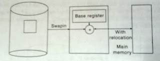
Relocation is a mechanism to convert the logical address into physical address. An address generated by CPU is said to be logical address and an address generated by Memory Manager is said to be physical address.


Physical address = Contents of Relocation Register + Logical Address


Relocation is necessary at the time of swap in a process from one backing store to main memory. Almost all times, the process occupies the same location at the time of swap in. But, sometimes it is not possible; as such the relocation is required. Consider the following fig:

Relocation

Fig: Relocation

    2. Protection:


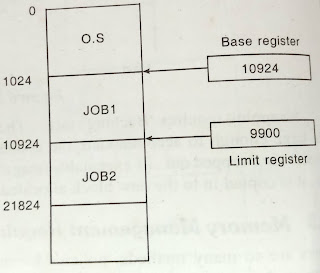
The word protection means provide security from unauthorized usage of memory. An OS can protect the memory with the help of a base and limit registers. Base registers consist of the starting address of the next process. The Limit registers specifies the boundary of that job. The Limit register is also said to be fencing register. Consider the following fig:


Main Memory Protection

Fig: Main Memory Protection

The base register holds the smallest legal physical memory address; the limit register contains the size of the process. Consider the below figure. It depicts the hardware protection mechanism with base and limit registers.


Memory protection with Base and Limit

Fig: Memory protection with Base and Limit


If the logical address is greater than the contents of a base register, it is authorized access, otherwise; it is a trap to operating system. If the physical address (logical + base) is less than the base limit, it causes no problems; otherwise it is a trap to the operating system.


3.    Sharing:


Generally, protection mechanisms are required at the time of access to the same portion of main memory by several processes. Accessing the same portion of main memory by a number of processes is said to be “sharing”. Suppose, to say if number of processes are executing same program, it is advantageous to allow each process to access same copy of the program rather than it having its own copy. If each process maintains a separate copy of that program, a lot of main memory will be wasted.


For ex: 3 users want to take their resumes using word processor. Then the 3 users share the word processor in the server; in the place of individual copy of word processor. Consider the following fig. that depicts the sharing of word processor.


Memory sharing

Fig: Memory sharing


4.    Logical Organization:


We know that main memory in a computer system is organized as a linear or one dimensional address space that consists of a sequence of bytes or words. Secondary memory, at its physical level, is similarly organized. Although this organization closely mirrors the actual machine hardware, it does not correspond to the way in which programs are typically constructed.


Most programs are organized into modules, some of which are modifiable (read only, execute only) and some of which contain data that may be modified. If the operating system and computer hardware can effectively deal with user programs and data in the form of modules of some sort, then a number of advantages can be realized.


 5.    Physical Organization:


A computer memory is organized into at least two levels: main memory and secondary memory. Main memory provides fast access at a relatively high cost. In addition, main memory is volatile i.e. it does not provide permanent storage. Secondary memory is slower and cheaper than main memory and it is usually not volatile. Thus, secondary memory of large capacity can be provided to allow for long-term storage of programs and data, while a smaller main memory holds programs and data currently in use.