Monday, 14 September 2020

Microkernel architecture in OS


Microkernels:


A microkernel is a software program loaded in main memory to perform some of the functions of the operating system so that the size of OS can be reduced. Microkernel provides process scheduling, memory management and communication services. Initially, microkernel approach was used in MACH Operating System. Later on, as its popularity increased, this approach was used in Windows 2000.


 Microkernel architecture:

Micro-kernel architecture

Fig: Microkernel architecture


In the microkernel architecture, essential and main operating system functions should be executed in the kernel mode. Remaining all i.e. less essential services and applications are built on microkernel and execute in user mode. In ordinary operating systems like layered operating systems, all the essential functions are executed in kernel mode only.


Microkernel is a minimal operating system that performs only the essential functions of an operating system. System processes perform all other operating system functions.


Benefits:


1.    Portability:  portability is the main feature of micro kernel. Microkernel can be suitable to any type of system. It also supports addition of new services.


2.    Flexibility:  microkernel architecture is flexible as existing features can be removed to produce a smaller and more efficient architecture.


3.    Uniform interfaces:  microkernel design imposes a uniform interface on requests made by a process.


4.    Extensibility:  the microkernel architecture can incorporate the new services as well as new hardware devices.


5.    Reliability:  as the size of software product increases, the reliability will decrease. Here, the microkernel reduces the size of operating system. So reliability will increase.


6.    Object Oriented: it supports object oriented OS.


Differences between Monolithic and Microkernel:

Monolithic Kernel

Microkernel

Kernel size is large.

Kernel size is small.

OS is complex to design.

OS is easy to design, implement and install.

Request may be serviced faster.

Request may be serviced slower compared to monolithic kernel.

All OS services are included in kernel.

Kernel provides only IPC and low level device management services.

No message passing and context switching is required while kernel is performing the job.

It requires message passing and context switching facilities.


Wednesday, 2 September 2020

User level and Kernel level threads in OS

  Process vs. Thread:

Parameter

Process

Thread

Sharing of memory and address space

It can't share same memory area i.e. address space.

Threads can share memory and files.

Time for creation

It takes more time to create a process.

It takes less time to create a thread.

Time for termination

Requires more time to complete the execution and termination of process

 Less time for termination.

Execution speed

Execution is very slow.

Execution is a very fast.

Time for switching

Requires more time to switch between two processes.

Requires less time to switch between two threads.

Communication

Implementing communication between processes is bit more difficult.

Communication between two threads is very easy to implement because threads share the same memory.

System calls

Required to communicate with each other.

System calls are not required.

Coupling

Process is loosely coupled.

Threads are tightly coupled.

Resource requirement

It requires more resources to execute.

Requires fewer resources, hence, called as lightweight process.

Parallelism

Processes are not suitable for parallel activities.

Suitable for parallel activities.


Thread Functionalities:


 Thread synchronization:


All threads within a process share the memory and files. If one thread is trying to modify one record in a file, it will affect with another threads. Hence, there is a need of mechanism for synchronizing the activities of thread.


User level and Kernel level threads:


 There are two main ways to implement threads:

1.    In user space and;

2.    In the kernel.


1.   User Level Threads:


These types of threads are loaded entirely in a user space; the kernel knows nothing about them. When Threads are managed in user’s space, each process needs its own private thread table. A thread table consists of the information of program counter, stack pointer, registers, state, etc.  The thread table is managed by runtime system. When a thread is moved to ready state or blocked state, the information needed to restart it is stored in the thread table.


User level thread


Advantages:


·         They allow each process to have its own scheduling algorithm.

·         Entire process is loaded in user space, so the process does not switch to the kernel mode to do thread management. This saves the overhead of two mode switches.

·         They can run on any operating system.


 Disadvantages:

·         When a user level thread executes a system call, not only the particular thread gets blocked but, all of the threads within the process are blocked.

·         In user level threads, only a single thread within a process can execute at a time. So, multiprocessing cannot be implemented.


2.   Kernel Level Threads:


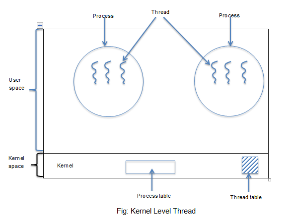
In kernel level threads, the kernel does total work of thread movement. There is no thread table in each process.  The kernel has a thread table that keeps track of all the threads in system. When a thread wants to create a new thread or destroy any existing thread, it makes a kernel call, which takes the action.


The kernel’s thread table holds each thread registers, state and their information. The information is saved as with user level threads, but it is now in the kernel instead of the user space.


Kernel level thread

Advantages:


·         The kernel can simultaneously schedule a multiple threads from the same process on multiple processors. This means it supports multiprocessing whereas, user level threads can't support this.

·         If a thread in a process is blocked; the kernel can schedule another thread of the same process.

·         The kernel routine themselves can be multithreaded.

·         Scheduling by kernel is done on a thread bus.


 Disadvantages:


·         More cost for creating and destroying threads in the kernel.

·         Transfer of control from one thread to another within the same process requires a mode switch to the kernel.


 3.   Combined approaches:


If we combine both approaches then we get the advantages of both. Some operating systems provide this type of facility. In combined system, thread creation is done completely in user space. Best example for this approach is Sun Solaris.


Thread Life Cycle and Multi-threading concepts in OS


Concepts of Threads:


A process is divided into number of lightweight process.  Each light weight process is said to be a thread.  The thread has a program counter that keeps the track of which instruction to execute next, it has a registers, which holds its current working variables.  It has a stack which contains the execution history.


Number of threads can share an address space, open files and other resources. Same as a number of processes can share their physical memory, disks, printers and other resources. Threads operates in many respects in the same manner as process as they have some of the properties of process.


Threads can be in one of several states: Ready, Blocked, Running Terminated.  Like process, threads share the CPU, and only one thread at a time is active or running. Threads can create a child threads. Unlike process, threads are not independent of one another. As all threads can access every address in the stack; a thread can read or write over any other thread stacks.


The programmer specifies that application contain ‘Threads of execution’. It describes each thread designating portion of program that may be executed concurrently with other threads. This capability is called multi-threading.


Life cycle of Thread:


A thread is said to be in one of the following several thread states:


·         Born state:  a thread has just been created.


·         Ready state:  the thread is waiting for CPU.


·         Running state:  the system assigns the processor to the thread.


·         Blocked state:  the thread is waiting for an event to occur or waiting for an IO device.


·         Sleep state: sleeping thread becomes ready after the designated sleep time expires.


·         Dead or Terminated state: the thread has finished its execution.


Thread Life Cycle


Multi-threading:


Single-threaded and multi-threaded process
Fig: Single-threaded and multi-threaded process


A process is divided into a number of smaller tasks; each task is called a thread. Number of threads within a process execute at a time. This is called as multi-threading.  Supporting of multithreading is the additional capability of an operating system. Based on the functionality, threads are divided into four categories. These are:


1.    One Process One Thread:

It is a traditional approach in which the process maintains only one thread. Hence, it is called single thread approach. For ex: MS DOS operating system supports this type of approach.


2.    One Process, Multiple Threads:

In this approach, a process is divided into a number of threads. Best example for this is a Java Runtime Environment (JRE).


3.    Multiple Process, One Thread Per Process:

An OS supports multiple user processes but only support one thread per process. UNIX is the best example of this.


4.    Multiple Processes, Multiple Threads Per Process:

In this approach, each process is divided into a number of threads. For ex: Windows 2000, Sun Solaris and Linux.


Advantages of a thread:


1.    A thread takes less time to terminate than a process.


2.    It takes less time to switch between two threads within the same process.


3.    It takes less time to create a new thread within the process.


4.    Efficient communication between threads is possible.

Tuesday, 1 September 2020

Entity - Relationship (E - R) Diagram in DBMS

 Entity - Relationship (E - R) Diagram:

The Entity Relationship (E-R) data model is based on a perception of a real world that consists of a collection of basic objects called entities and of relationships among these objects. An entity is a thing or object in the real world that is distinguishable from other objects. For example each person is an entity, and bank accounts can be considered as entities.


Entities are described in a database by a set of attributes. For example the attributes account number and balance may describe one particular account in a bank, and therefore some attributes of the account entity set. A relationship is an association among several entities. For example a deposit a relationship associates a customer with each account that he or she has.


The set of all entities of the same type and the set of all relationships of the same type are termed as entity set and relationship set respectively. The overall logical structure (schema) of a database can be expressed graphically by an ER diagram which is the built up from the following components:


·         Rectangles- it represent entity sets


·         Ellipses: it represents attributes


·         Diamonds: it represents relationship sets


·         Lines: it link attributes to entity sets and entity sets to relationship sets


·         Double ellipses: it represents multivalued attributes


·         Dashed ellipse:  it denote derived attributes


·         Double lines:  it indicate total participation of an entity in a relationship set


·         Double rectangles: it represents weak entity set


E-R Diagram example

Fig: E-R diagram example

Consider the entity relationship diagram in the above figure which consists of two entity sets, customer and loan, related through a binary relationship set borrower. The attributes associated with customer are customer-id, customer-name, customer-street, and customer-city. The attributes associated with loan are loan- number, and amount.


In fig. attributes of an entity set that are members of the primary key are underlined. The relationship set borrower may be one to one, one to many, many to one, or many to many. To distinguish among these relationship types, we draw either a directed line (->) for an undirected line(---) between the relationship set and entity set in question.


Symbols used in E-R diagram:

E-R Diagram Symbols


Mapping Cardinalities or Types of Relationships in DBMS:


Mapping Cardinalities / Types of Relationships:


Mapping cardinalities or cardinality ratios express the number of entities to which another entity set can be associated via a relationship set. Mapping cardinalities are most useful in describing binary relationship sets, although they can contribute to the description of relationship sets that involve more than two entity sets.


For a binary relationship set R, between entity sets A and B, the mapping cardinality must be one of the following:


A.   One-to-One  (1:1) :


An entity in A is associated with at most one entity in B, and an entity in B is associated with at most one entity in A. Such a relationship is called as one to one relationship.


One to One Relationship

Fig: One to One relationship


B.    One to Many(1:M) :


An entity in A is associated with any number (zero or more) of entities in B. An entity in B however, can be associated with at most one entity in A. Such a relationship is called as one to much relationship.


One to Many Relationship

Fig: One to Many relationship


C.    Many to One(M:1):


An entity in A is associated with at most one entity in B. An entity in B however, can be associated with any number (zero or more) of entities in A. Such a relationship is called as many to one relationship.


Many to One Relationship

Fig: Many to One relationship


For ex: consider the borrower relationship set. If in a particular bank a loan can belong to only one customer, and a customer can have several loans, then the relationship set from customer to loan is one to many.


D.    Many to Many(M:N):


An entity in A is associated with any number (zero or more) of entities in B, and an entity in B is associated with any number (zero or more) of entities in A. Such a relationship is called as many to many relationship.


Many to Many Relationship

Fig: Many to Many relationship

For ex: if a loan can belong to several customers (as loans is taken jointly by several business partners), the relationship set is many to many.


Tuesday, 25 August 2020

What is an attribute? What are the various types of attributes?


Attribute and its various types:


 Attribute:


An entity is represented by a set of attributes. Attributes are descriptive properties possessed by each member of an entity set. Each entity has a value for each of its attributes. For ex: a particular customer entity may have the value 12345 for Customer-ID.


For each attribute there is a set of permitted values called the domain, or value set of that attribute. The domain of attribute customer name might be the set of all text strings of a certain length.


Types of attributes:


1.    Simple and Composite Attribute:


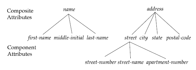
If attributes cannot be further divided into sub-parts then they are known as simple attribute. Composite attributes on the other hand can be divided into sub parts. For ex: an attribute name would be structured as a composite attribute consisting of First-name, Middle-name, and Last-name.


Composite attribute

Fig: Example of composite attributes


2.    Single and Multi-valued attributes:


The Loan-number attribute for a specific loan entity refers to only one loan number. Such attribute is called as single valued attribute. There may be instances where an attribute has a set of values for a specific entity. Consider an employee entity set with the attribute phone number. An employee may have zero, one or several phone numbers and different employees may have different numbers of phones. This type of attribute is said to be multi-valued attribute.


3.    Derived attributes:


The value for this type of attribute can be derived from the values of other related attributes or entities. As an example, suppose that the Customer entity set has an attribute age which indicates the customer’s age. If the customer entity set also has an attribute date-of-birth, we can calculate age from date of birth and the current date. So, age is a derived attribute. In this example, date-of-birth may be referred as a base attribute.


Composite, multi-valued and derived attributes

Fig: Example of composite, multi-valued and derived attributes


4.     Null attribute:


An attribute takes a null value when an entity does not have a value for it. Null value may indicate not applicable, i.e. the value does not exist for the entity. For ex: one may have no middle name. Null can also designate that an attribute value is unknown. An unknown value may be either missing or not known.